Truck oil-to-electric hybrid solution
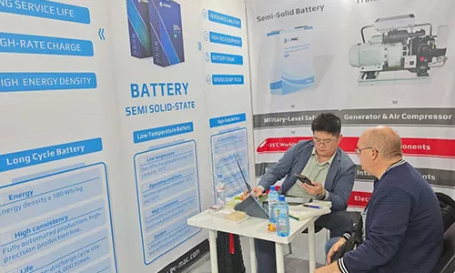
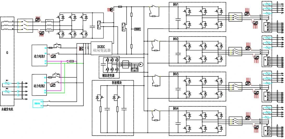
The electric drive system of the mining truck consists of a power system, a traction system, a braking system, an energy storage system, a cooling system, etc.
- Power system: diesel engine + generator
- Traction system: inverter + traction motor
- Braking system: brake resistor
- Energy storage system: lithium iron phosphate battery
- Cooling system: water tank + water pump
The three-phase AC power of the generator is rectified by the PWM rectifier and connected in parallel with the power battery through the DC/DC power system. When the bus voltage is greater than the set voltage of the DCDC output terminal, the DCDC is reversely charged; when the bus voltage is less than its set voltage, it is forward discharged; when the bus voltage is higher than the chopper voltage, the braking resistor is put into operation.
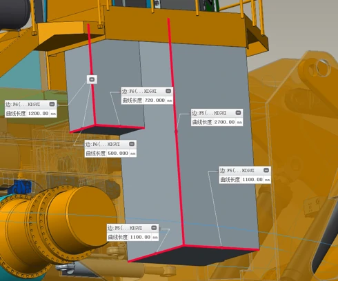
Electrical Cabinet
Integrated generator controlled rectifier, drive motor inverter, bidirectional DCDC, and distributor;
The internally integrated controller, auxiliary drive, power distribution and DCDC are all automotive-grade products. They are integrated into a cabinet through design, with electrical and water interfaces left on the outside for easy installation in the vehicle.
Serial Number |
Name |
Model |
Quantity |
| 1 | Generator Controller | SA500 | 2 |
| 2 | Drive Motor Controller | SA500 | 4 |
| 3 | Bidirectional DCDC | / | 1 |
| 4 | High – voltage Power Distribution | / | 1 |
| 5 | Auxiliary Drive | / | 1 |
| ——END—— | |||
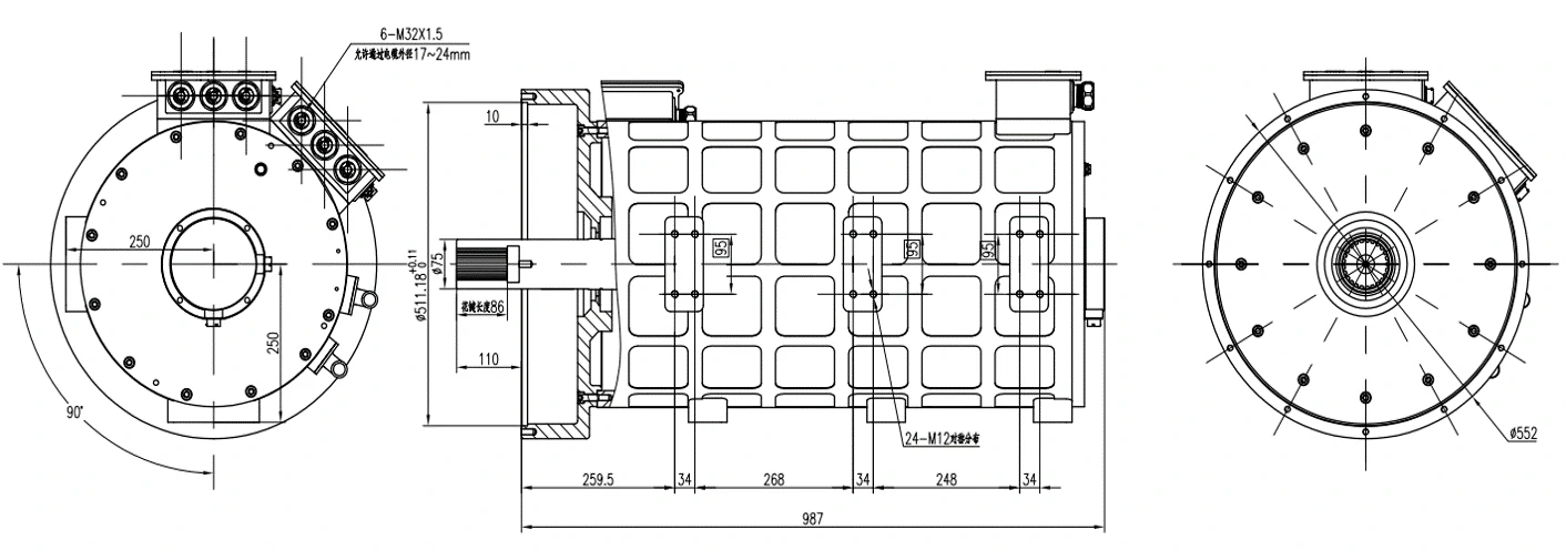
Permanent magnet generator (matching two controllers)
Item |
Parameter Requirements |
| 1. Motor Model | TZ400XS020A |
| 2. Rated Voltage (VDC) | 620 |
| Rated / Peak Power (kW) | 2X250 / 2X360 |
| Rated / Peak Torque (N·m) | 2X1200 / 2X2400 |
| Rated / Maximum Speed (rpm) | 1989 / 3000 |
| Rated / Peak Current (A) | 2X370 / 2X700 |
| Frequency Range | 0 – 300Hz |
| Duty Cycle | S9 |
| Connection | Y |
| Insulation Class | H – class |
| Protection Class | IP69 |
| Transmission Method | Spline Transmission |
| Cooling Method | Water – cooled |
| 3. Cooling Water Flow Rate | 2X20 L/min |
| ——END—— | |
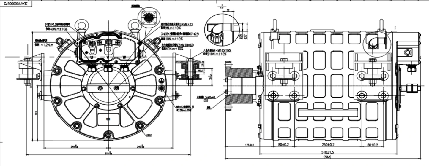
Model | TZ380XS018A |
| Type | Permanent Magnet Synchronous Motor |
| Dimensions (mm) | Φ434×510 (Refer to the drawing) |
| Weight (Kg) | 310 |
| Maximum Speed / Rated Speed (r/min) | 2721 / 1036 |
| Peak Torque / Rated Torque (N.m) | 4275@60S / 1383@30M |
| Peak Power / Rated Power (kW) | 282 / 150 @627VDC |
| ——END—— | |
Permanent magnet drive motor (matching four controllers)
Controller

Item | Detailed Specification |
| Motor Controller Model | KTZ57X85S001 |
| Applicable Motor Type | Three – phase AC Synchronous Motor |
| Rated Voltage | 576 V |
| Rated Power | 300 kW |
| Rated Output Current | 450A |
| Peak Output Current | 800 A |
| Withstand Maximum Back EMF of Motor | The module uses 1200V withstand voltage, derated by 90% corresponding to 1080V |
| Controller Efficiency under Rated Conditions | ≥98% |
| ——END—— | |
Item |
Detailed Specification |
| Model | / |
| Rated Input Voltage | 380 V |
| Rated Power | 200 kW |
| Rated Input Current | 530A |
| Output Voltage | 400 – 750V |
| ——END—— | |
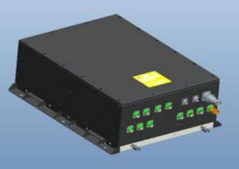
| Braking Unit | ||||
| Rated Voltage | DC730V | |||
| Peak Power of Braking Unit | 2×600kW | |||
| Resistance Value (at 20°C) | 2×2.4Ω, ±5% | |||
| Duty Cycle | Intermittent operation, short – time repeated | |||
| Housing Material | Stainless steel | |||
| Resistance Band Material | Cr20Ni35 | |||
| Cooling Method | Moving – air cooling | |||
| Protection Level | IP20 (Terminal box part is IP54) | |||
| ——END—— | ||||
System bus Design:CAN Topology
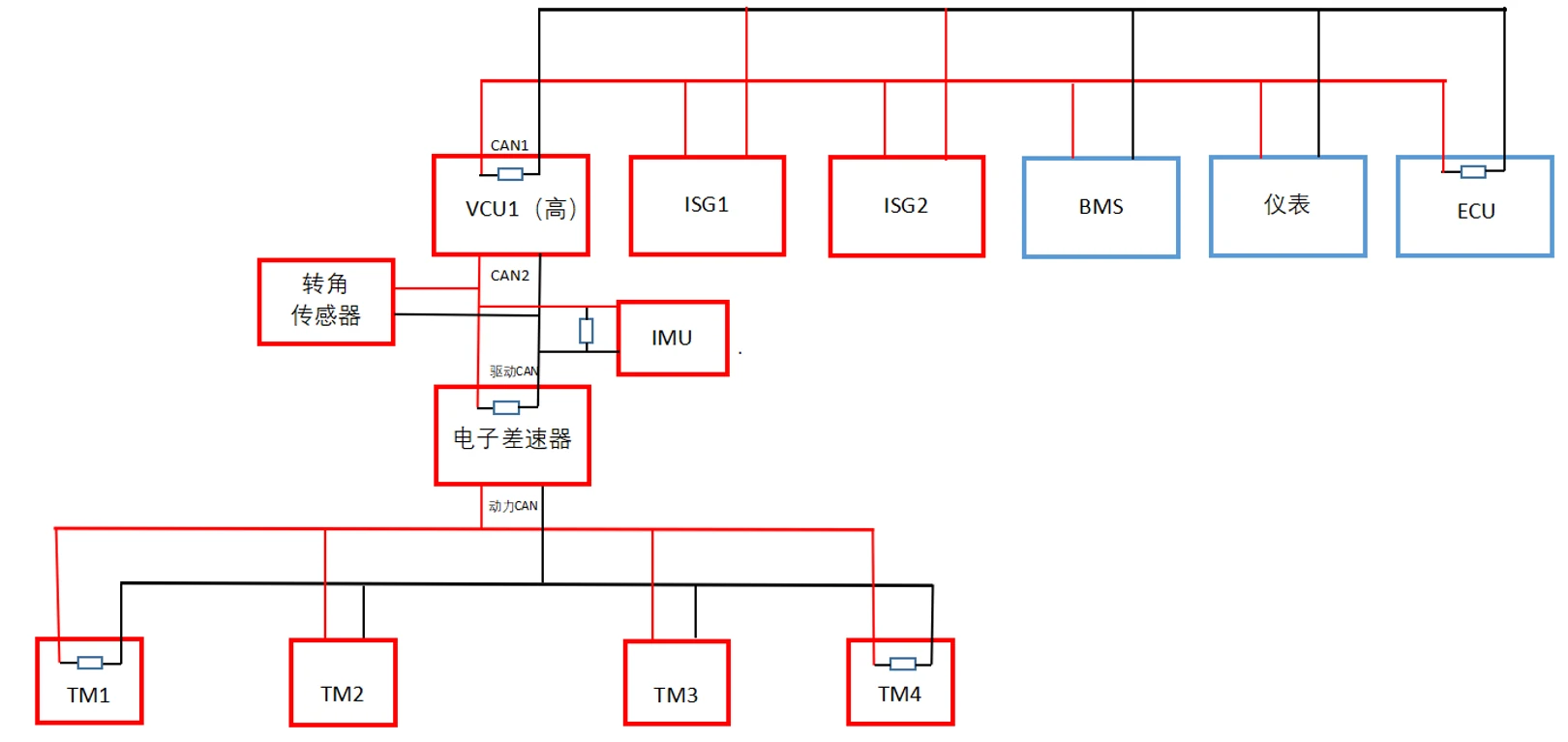
Drive
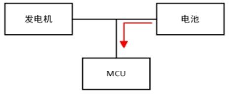
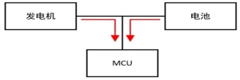
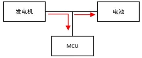
The motor drive has two energy sources, which can be divided into the following three forms:
- Battery powered
- Battery and generator power supply at the same time
- Generator power only
- When the battery is the only source of energy, the generator power is 0, and all the energy is provided by the battery.
- When the battery and the generator supply energy at the same time, the generator power is closed-loop controlled by the PI regulator to adjust the power distribution between the generator and the battery.
- Only the generator provides energy, and part of the generator energy is recharged into the battery.
Giving Back
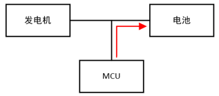
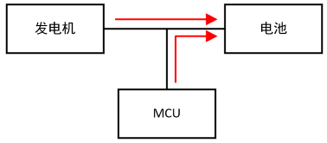
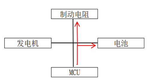
Motor feedback conditions are divided into the following three forms:
- Only MCU recharges the battery
- MCU and generator together to recharge the battery
- MCU recharges battery and brake resistor
- When only the MCU recharges the battery, the generator power is 0, the battery is in the charging state, and the MCU feedback power is limited by the current chargeable current limit of the battery.
- When the MCU and the generator recharge current together, the MCU recharge power is limited by the battery’s allowable charging power. At the same time, the generator’s power generation is limited by the remaining charging power after deducting the MCU’s current recharge power from the battery’s allowable charging power.
- The MCU brakes at high power, exceeding the allowable charging current of the battery. At this time, the battery charging current is controlled constantly through the DCDC output. Excessive current will raise the bus voltage until the braking unit starts.
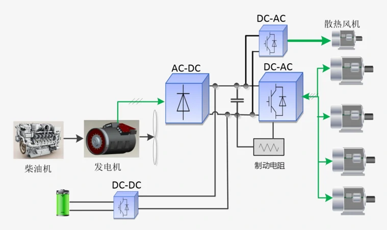
Energy allocation strategy
